Ordering Instructions
![]()
| ① Model Name | ② Specification Code | ③ Reduction Ratio | ④ Structure Code | ⑤ Generator Type | ⑥ Custom Specification |
| NLGS NCGS NCGD NLGD NLGST | 11 | | 50 | | 100 | | | C U | I II III IV V | E001 |
| 14 | 30 | 50 | 80 | 100 | | |
| 17 | 30 | 50 | 80 | 100 | 120 | |
| 20 | | 50 | 80 | 100 | 120 | 160 |
| 25 | | 50 | 80 | 100 | 120 | 160 |
| 32 | | 50 | 80 | 100 | 120 | 160 |
| 40 | | 50 | 80 | 100 | 120 | 160 |
(1)Production
Location:N is the factory codeFlexspline Shape:Flexsplines are divided
into L top hat type and C cup typeFlexspline Length:Flexsplines are
divided into S standard type and D short tube typeHigh Torque Design:G
for high torque design,blank for standard typeSpecial Structure:T for
three-wave generator structure Gearbox
(2)Specification Codes of Strain Wave Gearboxes:Such as 14,17,20,25,32,40,etc.
(3)Reduction Ratios of Strain Wave Gearboxes:Such as 30,50,80,100,120,160,etc.
(4)Structure Code
(5)Wave Generator Type:C for component type,U for combined type
(6)E001 is the project code for customized Strain Wave Gearboxes
Key Features
High
precision: multiple teeth mesh at the same time in two 180 degree
symmetric positions, so the gear pitch error and cumulative pitch error
have a relatively average impact on the rotation accuracy, and can
obtain very high position accuracy and rotation accuracy.
Large
transmission ratio: the transmission ratio of single-stage strain wave
gear transmission can reach i=30-500, and the structure is simple. Three
basic parts on the same axis can achieve high speed ratio.
High
bearing capacity: in the strain wave transmission, the meshing of teeth
and tooth surface contact, plus the number of meshing teeth at the same
time is relatively large, so the unit area load is small, and the
bearing capacity is higher than other transmission forms.
Small
size and light weight: compared with the ordinary gear device, the
volume and weight can be greatly reduced to achieve miniaturization and
lightweight.
High transmission efficiency and long service life.
Smooth transmission, no impact, and low noise.
Gearbox Technical Specifications
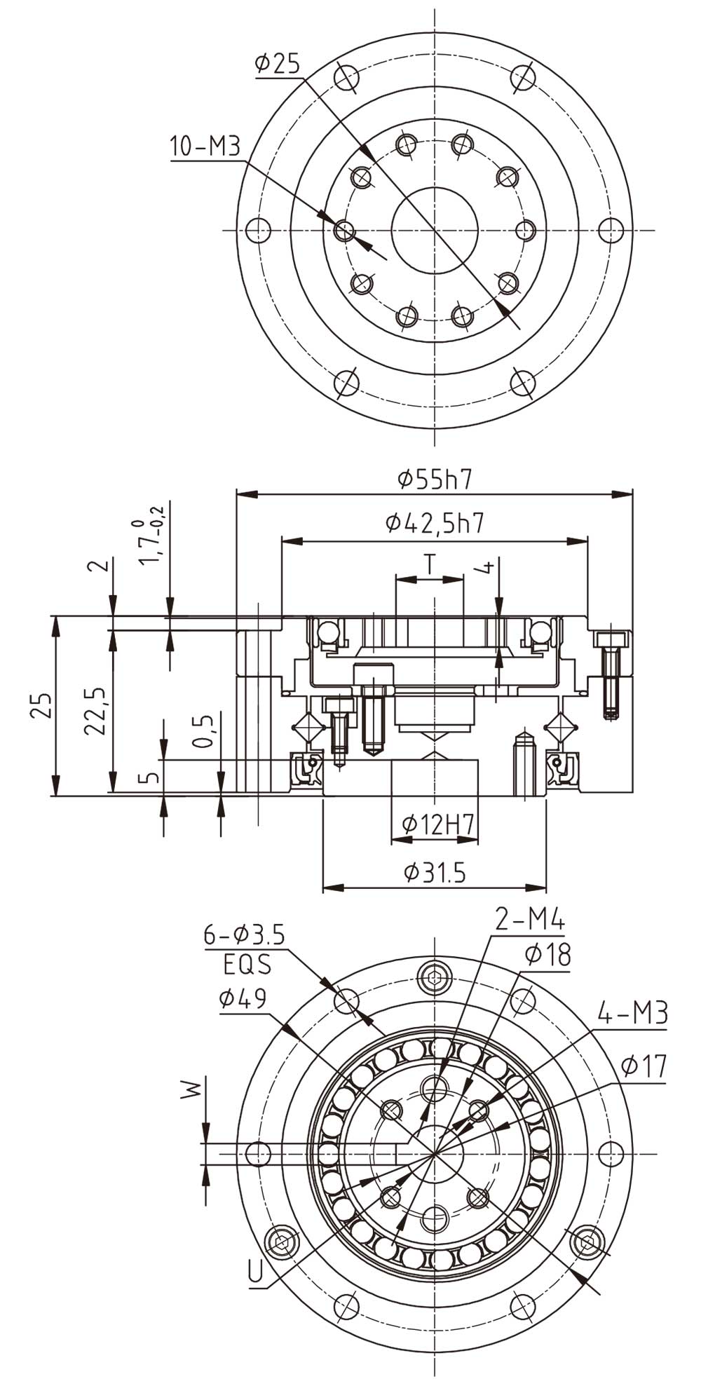
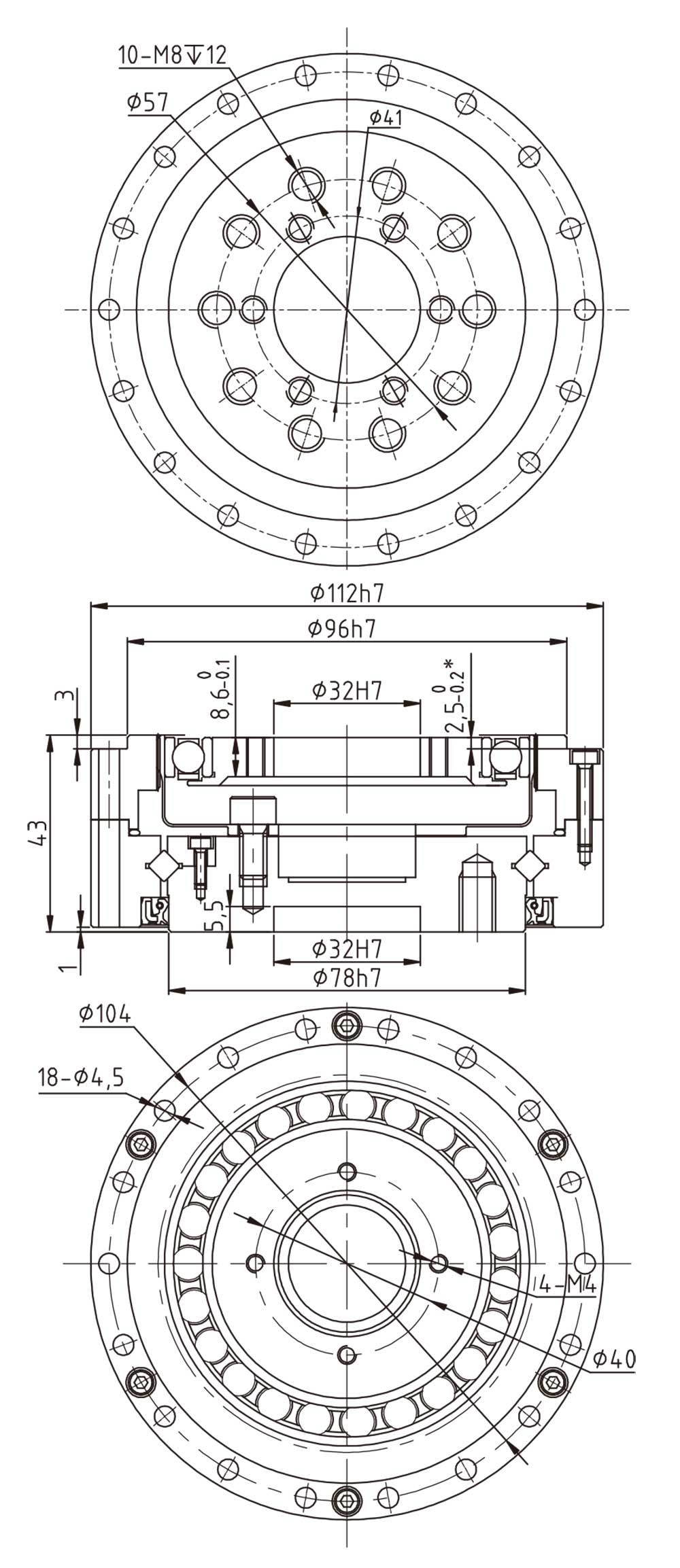
NCGD-14-00-U-I Type Strain Wave Gearbox
![]()
| MODEL | U | T | W |
| Wave generator-A Ø6 | Ø6H7 | 7+0.10 | 2P9/JS9 |
| Wave generator-A Ø8 | Ø8H7 | 9.4+0.10 | 3P9/JS9 |
| Wave generator-A Ø11 | Ø11H7 | 12.8+0.10 | 4P9/JS9 |
| Wave generator-A Ø11 | Ø11H7 | | |
| ModelItem | Gear Ratio | Rated Speed at 2000 r/min Input | Max. Allowable Torque during Start/Stop | Max. Allowable Average Load Torque | Max. Momentary Allowable Torque | Max. Allowable Input Speed | Allowable Average Input Speed | Starting Torque | Backlash | Service Life | Weight |
| Nm | Nm | Nm | Nm | rpm | rpm | cNm | arcsec | Hour | Kg |
| NCGD–14 | 50 | 3.7 | 12 | 4.8 | 23 | 8500 | 3500 | 4.4 | ≤20 | 9000 | 0.64 |
| 80 | 5.4 | 16 | 7.7 | 35 | 3.2 | ≤20 | 10000 |
| 100 | 5.4 | 19 | 7.7 | 35 | 2.8 | ≤20 | 10000 |
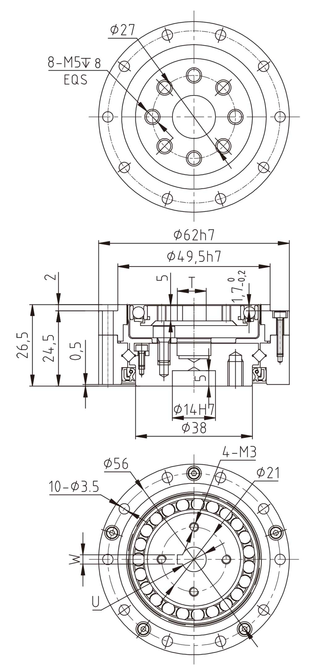
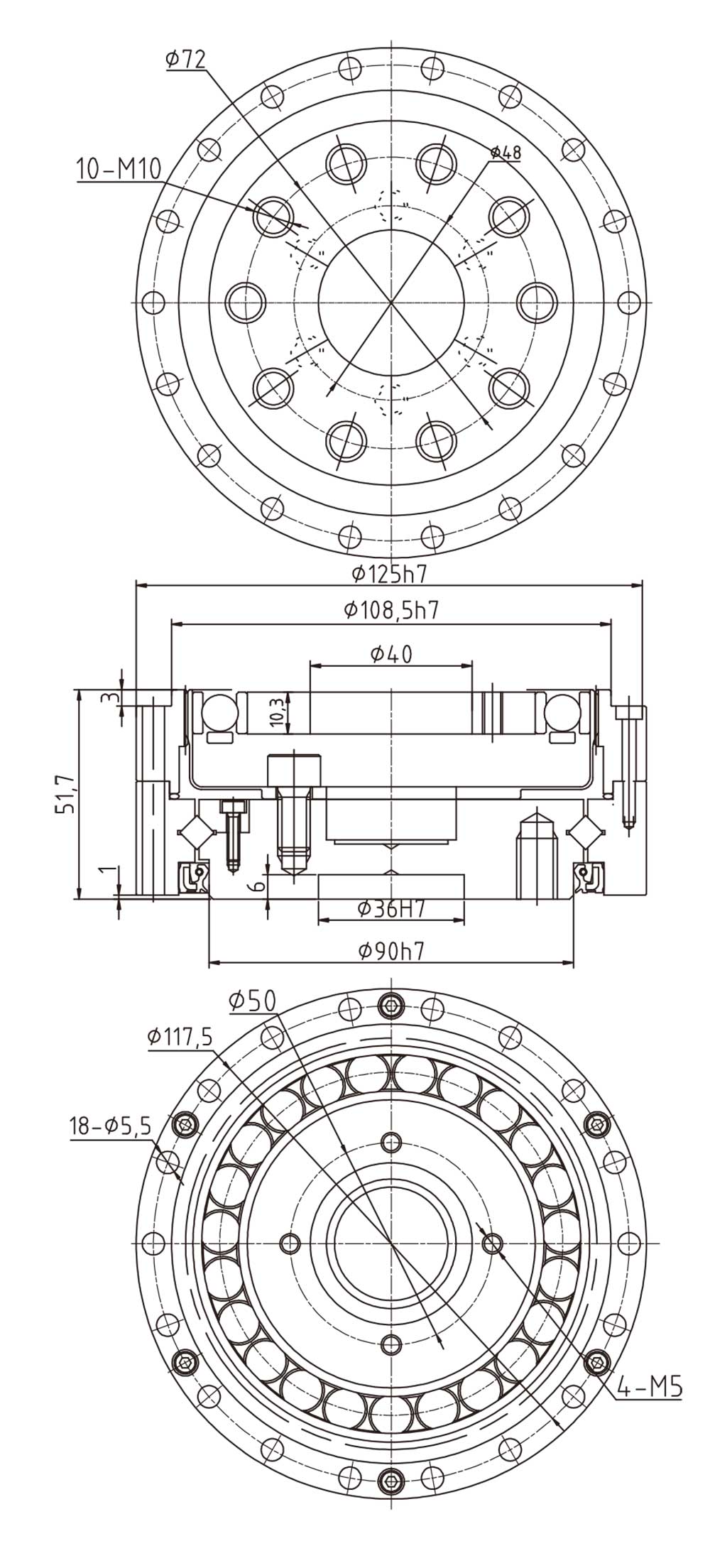
NCGD-17-00-U-I Type Strain Wave Gearbox
![]()
| MODEL | U | T | W |
| Wave generator-A Φ8 | Φ8H7 | 9.4+0.10 | 3P9/JS9 |
| Wave generator-A Φ11 | Φ11H7 | 12.8+0.10 | 4P9/JS9 |
| Wave generator-A Φ15 | Φ11H7 | | |
| ModelItem | Gear Ratio | Rated Speed at 2000 r/min Input | Max. Allowable Torque during Start/Stop | Max. Allowable Average Load Torque | Max. Momentary Allowable Torque | Max. Allowable Input Speed | Allowable Average Input Speed | Starting Torque | Backlash | Service Life | Weight |
| Nm | Nm | Nm | Nm | rpm | rpm | cNm | arcsec | Hour | Kg |
| NCGD–17 | 50 | 11 | 23 | 18 | 48 | 7300 | 3500 | 6.7 | ≤20 | 9000 | 0.46 |
| 80 | 15 | 29 | 19 | 61 | 4.4 | ≤20 | 10000 |
| 100 | 16 | 37 | 27 | 71 | 3.8 | ≤20 | 10000 |
| 120 | 16 | 37 | 27 | 71 | 3.6 | ≤20 | 10000 |
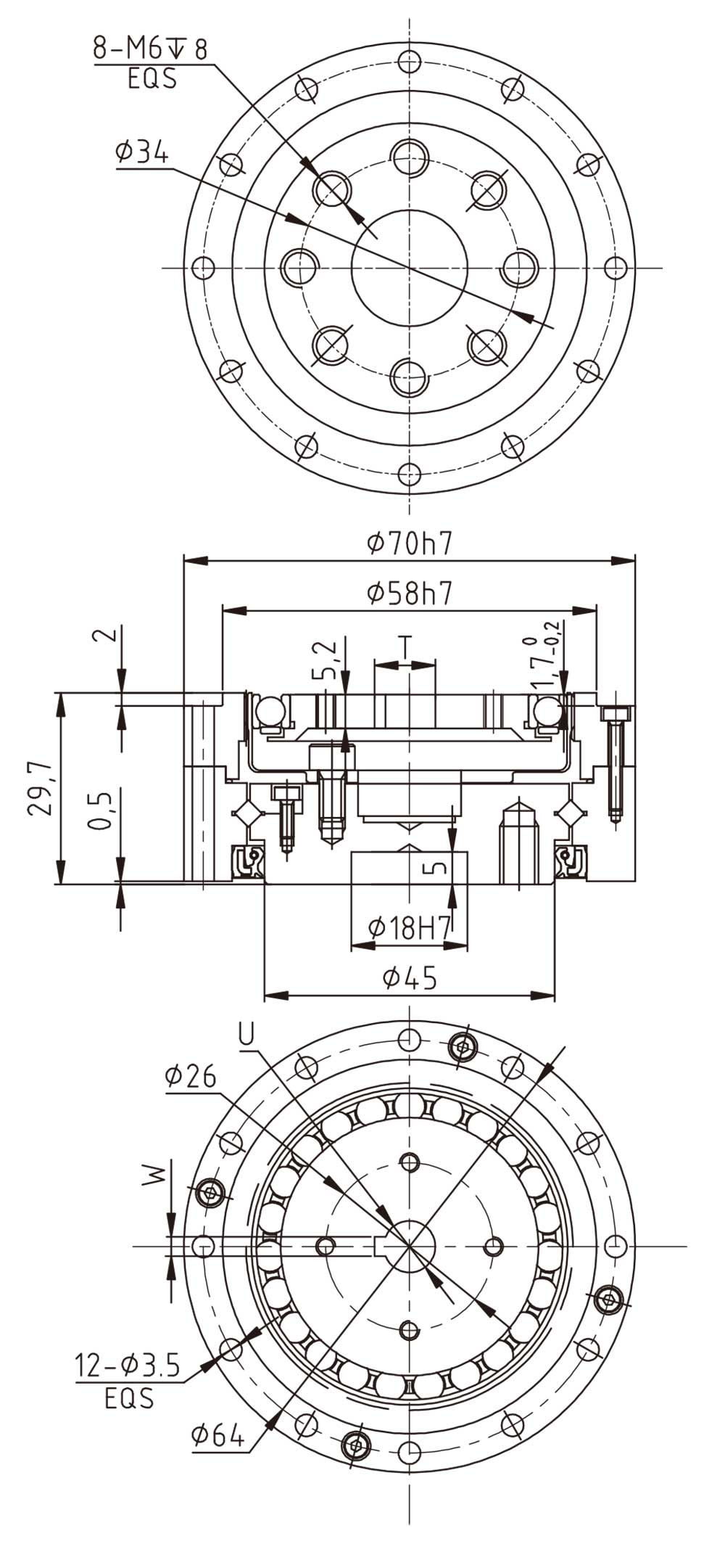
NCGD-20-00-U-I Type Strain Wave Gearbox
![]()
| MODEL | U | T | W |
| Wave generator-A Ø8 | Ø8H7 | 9.4+0.10 | 3P9/JS9 |
| Wave generator-A Ø11 | Ø11H7 | 12.8+0.10 | 4P9/JS9 |
| Wave generator-A Ø14 | Ø14H7 | 16.3+0.10 | 5P9/JS9 |
| Wave generator-A Ø20 | Ø20H7 | | |
| ModelItem | Gear Ratio | Rated Speed at 2000 r/min Input | Max. Allowable Torque during Start/Stop | Max. Allowable Average Load Torque | Max. Momentary Allowable Torque | Max. Allowable Input Speed | Allowable Average Input Speed | Starting Torque | Backlash | Service Life | Weight |
| Nm | Nm | Nm | Nm | rpm | rpm | cNm | arcsec | Hour | Kg |
| NCGD-20 | 50 | 17 | 39 | 24 | 69 | 6500 | 3500 | 8.9 | ≤20 | 9000 | 0.65 |
| 80 | 24 | 51 | 33 | 89 | 5.7 | ≤20 | 10000 |
| 100 | 28 | 57 | 34 | 95 | 5.1 | ≤20 | 10000 |
| 120 | 28 | 60 | 34 | 95 | 4.5 | ≤20 | 10000 |
| 160 | 28 | 64 | 34 | 95 | 3.9 | ≤20 | 10000 |
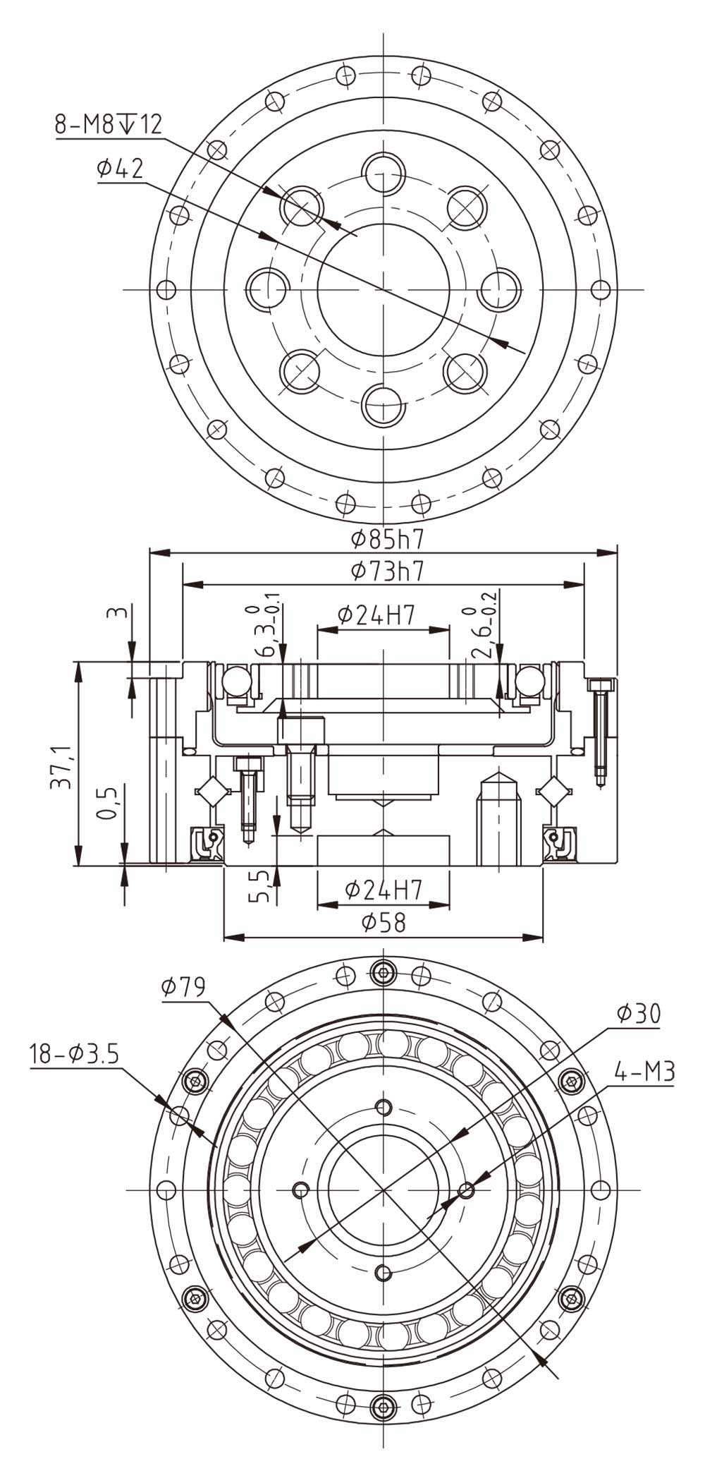
NCGD-25-00-U-I Type Strain Wave Gearbox
![]()
| ModelItem | Gear Ratio | Rated Speed at 2000 r/min Input | Max. Allowable Torque during Start/Stop | Max. Allowable Average Load Torque | Max. Momentary Allowable Torque | Max. Allowable Input Speed | Allowable Average Input Speed | Starting Torque | Backlash | Service Life | Weight |
| Nm | Nm | Nm | Nm | rpm | rpm | cNm | arcsec | Hour | Kg |
| NCGD-25 | 50 | 27 | 69 | 38 | 127 | 5600 | 3500 | 16 | ≤20 | 9000 | 1.2 |
| 80 | 44 | 96 | 60 | 179 | 10 | ≤20 | 10000 |
| 100 | 47 | 110 | 75 | 184 | 9.1 | ≤20 | 10000 |
| 120 | 47 | 117 | 75 | 204 | 8.2 | ≤20 | 10000 |
| 160 | 47 | 123 | 75 | 204 | 7.2 | ≤20 | 10000 |
NCGD-32-00-U-I Type Strain Wave Gearbox
![]()
| ModelItem | Gear Ratio | Rated Speed at 2000 r/min Input | Max. Allowable Torque during Start/Stop | Max. Allowable Average Load Torque | Max. Momentary Allowable Torque | Max. Allowable Input Speed | Allowable Average Input Speed | Starting Torque | Backlash | Service Life | Weight |
| Nm | Nm | Nm | Nm | rpm | rpm | cNm | arcsec | Hour | Kg |
| NCGD-32 | 50 | 53 | 151 | 75 | 268 | 4800 | 3500 | 32 | ≤20 | 9000 | 2.4 |
| 80 | 83 | 213 | 117 | 398 | 22 | ≤20 | 10000 |
| 100 | 96 | 233 | 151 | 420 | 20 | ≤20 | 10000 |
| 120 | 96 | 247 | 151 | 445 | 17 | ≤20 | 10000 |
| 160 | 96 | 261 | 151 | 445 | 15 | ≤20 | 10000 |
NCGD-40-00-U-I Type Strain Wave Gearbox
![]()
| ModelItem | Gear Ratio | Rated Speed at 2000 r/min Input | Max. Allowable Torque during Start/Stop | Max. Allowable Average Load Torque | Max. Momentary Allowable Torque | Max. Allowable Input Speed | Allowable Average Input Speed | Starting Torque | Backlash | Service Life | Weight |
| Nm | Nm | Nm | Nm | rpm | rpm | cNm | arcsec | Hour | Kg |
| NCGD-40 | 50 | 96 | 281 | 137 | 480 | 4000 | 3000 | 55 | ≤20 | 10000 | 3.6 |
| 80 | 144 | 364 | 198 | 686 | 36 | ≤20 | 10000 |
| 100 | 185 | 398 | 260 | 700 | 32 | ≤20 | 10000 |
| 120 | 205 | 432 | 315 | 765 | 29 | ≤20 | 10000 |
| 160 | 206 | 453 | 316 | 765 | 26 | ≤20 | 10000 |
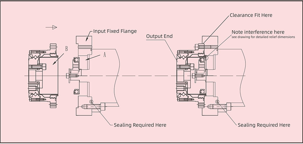
Installation Methods
![]()
Apply grease to the wave generator,gearbox inner cavity,and connecting flange cavity.
Fix the motor and flange,adding a sealing ring if necessary.
Securely fasten the wave generatorto the motor shaft end (note wave generator orientation),fixing with screws and flat washers.
Slowly rotate the wave generator and insert it into the gearbox,then connect the gearbox to the motor flange.
Note:
(1).Please manufacture the flange according to the installation precision requirements on page P23.
(2).It is recommended to use 12.9 high-strength screws with thread locking adhesive for tightening.
(3).After
installing the wave generator into the gearbox,it is recommended to run
the motor at low speed(100r/min)for aperiod before tightening the
screws.
(4).Design the flange cavity dimensions according to page P23 and fill with specified grease.
(5).Refer to the screw tightening torque table on page P22 for tightening torque.